High Frequency, High Current Spring Probe Catalog
Spring Probe Product Line
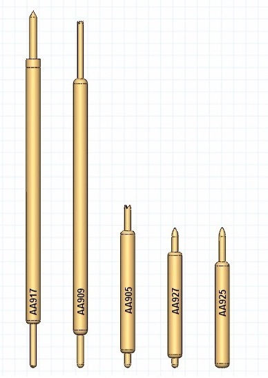
AA Series - 0.3mm (.0118) Pitch
|
AA Series 0.3mm (.0118) pitch |
|||||||||
|
Probe Series |
Initial Length |
Operating Position |
Operating |
Self |
Insertion Loss |
Typical Contact |
Maximum |
||
|
(inch/mm) |
(inch/mm) |
||||||||
|
.219 |
5.57 |
.199 |
5.05 |
18-20 grams |
1.0 nH |
37.1 GHz |
100 mOhms |
1.32 A |
|
|
.215 |
5.45 |
.193 |
4.90 |
12-17 grams |
1.54 nH |
12.0 GHz |
72 mOhms |
0.95A |
|
| AA905 | .100 | 2.54 | .086 | 2.18 | 20 grams | 0.54 nH | >40 GHz | 110 mOhms | 1.43 A |
| AA925 | CALL | CALL | 18 grams | - | - | 65 mOhms | 1.1 A | ||
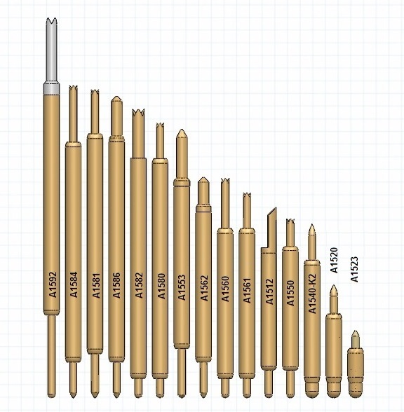
A Series - 0.4mm (.0157) Pitch
|
A Series 0.4mm (.0157) pitch |
|||||||||
|
Probe Series |
Initial Length |
Operating Position |
Operating Spring Force |
Self Inductance |
Insertion Loss < -1db to |
Typical Contact Resistance |
Maximum Current |
||
|
(inch/mm) |
(inch/mm) |
||||||||
|
A1592 |
.276" |
7.01 |
.242" |
6.15 |
30g |
- |
- |
- |
- |
|
A1584 |
.227" |
5.76 |
.199" |
5.05 |
30 g |
- |
- |
- |
- |
|
A1581 |
.224" |
5.69 |
.192" |
4.88 |
31 g |
- |
- |
- |
- |
|
.219” |
5.56 |
.199” |
5.06 |
19-20g |
- |
- |
80 mOhms |
1.68 A |
|
|
.210” |
5.33 |
.184” |
4.67 |
16-30g |
0.93 nH |
9.6 GHz |
100 mOhms |
1.4 A |
|
|
.210” |
5.33 |
.192” |
4.88 |
16-32g |
1.02 nH |
7.4 GHz |
95 mOhms |
1.55 A |
|
|
A1553 |
.195" |
4.95 |
.171" |
4.35 |
20 g |
- |
- |
- |
- |
|
.160” |
4.06 |
.144” |
3.66 |
14-30g |
0.80 nH |
11.6 GHz |
90 mOhms |
1.45 A |
|
|
A1560 |
.159" |
4.04 |
.141" |
3.58 |
22 g |
- |
- |
- |
- |
|
.149” |
3.78 |
.131” |
3.33 |
16-29g |
0.67 nH |
7.4 GHz |
90 mOhms |
1.65 A |
|
|
.131" |
3.32 |
.119" |
3.02 |
18-29 g |
0.66 nH |
20.3 GHz |
72 mOhms |
2.0 A |
|
|
.133” |
3.30 |
.118” |
3.00 |
20-29g |
0.71 nH |
18.7 GHz |
85 mOhms |
2.0 A |
|
|
.126" |
3.20 |
.114" |
2.90 |
22-29g |
0.42 nH |
16.1 GHz |
20 mOhms |
4.3 A |
|
|
.081” |
2.05 |
.075” |
1.90 |
20g |
0.44 nH |
24.1 GHz |
60 mOhms |
2.0 A |
|
| A1523 | CALL | CALL | 11 g | - | >40 GHz | - | - | ||
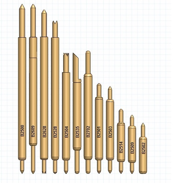
B Series - 0.5mm (.0197) Pitch
|
B Series 0.5mm (.0197 inch) Pitch |
|||||||||
|
Probe Series |
Initial Length |
Operating Position |
Spring Force |
Self Inductance |
Insertion Loss <-1db to |
Typical Contact Resistance |
Maximum Current |
||
| (inch / mm) |
(inch / mm) |
||||||||
|
.304” |
7.72 |
.275” |
6.99 |
28 g |
1.73 nH |
6.4 GHz |
80 mOhms |
2.6 A |
|
|
B2609 |
.304" |
7.72 |
.275" |
6.99 |
24 g |
- |
- |
- |
- |
| .274" | 6.96 | .254" | 6.45 | 28-35 g | - | - | - | - | |
|
.214” |
5.42 |
.190” |
4.82 |
24-34 g |
1.12 nH |
8.8 GHz |
60 mOhms |
2.9 A |
|
|
.217" |
5.50 |
.199” |
5.05 |
26-31 g |
- |
- |
55 mOhms |
2.3 A |
|
|
B2702 |
.224" |
5.70 |
.199" |
5.05 |
21 g |
- |
- |
- |
- |
|
.157” |
3.99 |
.142” |
3.61 |
26-32 g |
0.71 nH |
13.0 GHz |
60 mOhms |
1.7 A |
|
|
.162” |
4.11 |
.150” |
3.81 |
20-35 g |
0.97 nH |
11.2 GHz |
50 mOhms |
2.8 A |
|
|
.116” |
2.95 |
.104” |
2.64 |
26 g |
0.63 nH |
12.2 GHz |
90 mOhms |
2.0 A |
|
|
.108” |
2.74 |
.094” |
2.39 |
26 g |
0.60 nH |
13.2 GHz |
90 mOhms |
2.0 A |
|
|
.091” |
2.31 |
.085” |
2.16 |
32 g |
0.54 nH |
17.0 GHz |
30 mOhms |
1.5 A |
|
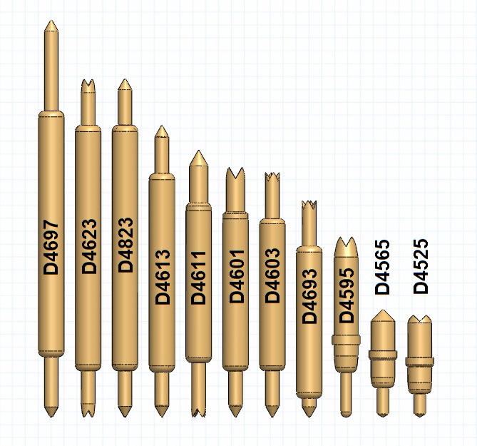
D Series - 0.8MM (.0315) Pitch
|
D Series 0.8mm (.0315) pitch |
|||||||||
|
Probe Series |
Initial Length |
Operating Position |
Spring |
Self |
Insertion Loss |
Typical Contact |
Maximum |
||
|
(inch/mm) |
(inch/mm) |
||||||||
|
.339” |
8.61 |
.295” |
7.50 |
32 g |
2.01 nH |
8.6 GHz |
45 mOhms |
2.6 A |
|
|
.289" |
7.33 |
.253” |
6.43 |
34 g |
1.55 nH |
8.2 GHz |
60 mOhms |
5.4 A |
|
|
D4823 |
.289" |
7.33 |
.253” |
6.43 |
28 g |
- |
- |
- |
- |
|
.249" |
6.32 |
.213-.216" |
5.49 |
24-34 g |
1.25 nH |
14.3 GHz |
40 mOhms |
2.15 A |
|
|
.214" |
5.43 |
.186" |
4.72 |
24-34 g |
1.0 nH |
12.8 GHz |
50 mOhms |
6.0 A |
|
|
.209" |
5.30 |
.181" |
4.59 |
24 g |
1.16 nH |
12.4 GHz |
70 mOhms |
4.0 A |
|
|
.185” |
4.71 |
.157” |
4.00 |
24-34 g |
0.92 nH |
18.3 GHz |
40 mOhms |
3.0 A |
|
|
.185” |
4.71 |
.157” |
4.00 |
23-36 g |
0.80 nH |
12.8 GHz |
40 mOhms |
3.0 A |
|
|
.154" |
3.91 |
.128" |
3.25 |
38 g |
0.82 nH |
19.5 GHz |
30 mOhms |
3.0 A |
|
|
D4565 |
.092" |
2.33 |
.071" |
1.80 |
30 g |
0.5 nH |
17.0 GHz |
25 mOhms |
6.0 A |
|
.087" |
2.21 |
.071" |
1.80 |
30 g |
0.48 nH |
38.5 GHz |
20 mOhms |
6.0 A |
|
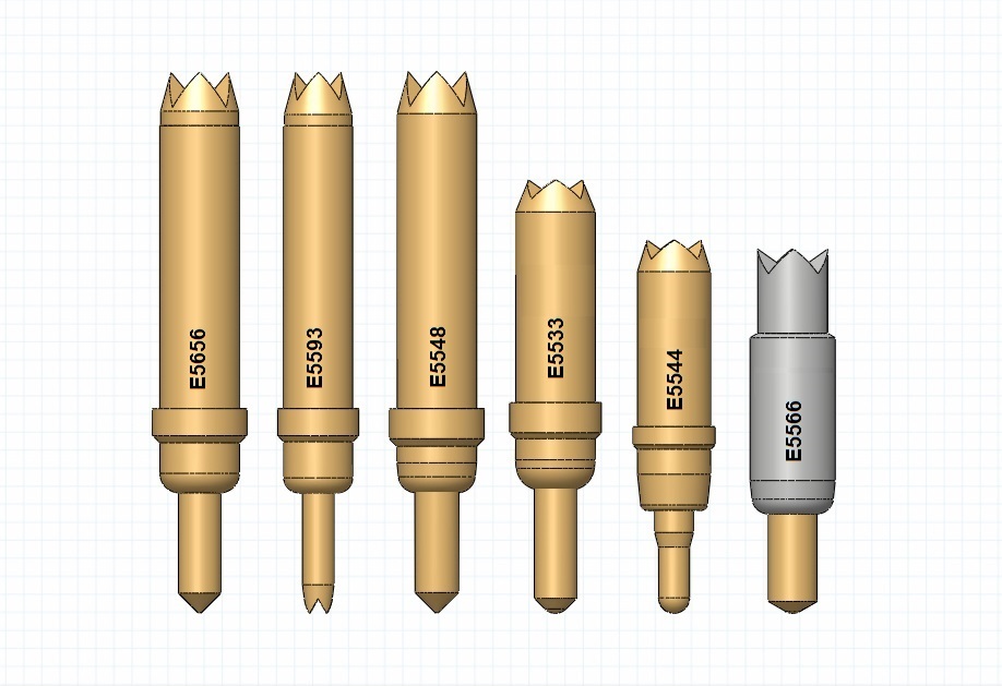
E Series - 1.0MM (.0394) Pitch
|
E Series 1.0mm (.0394) pitch |
|||||||||
|
Probe Series |
Initial Length (inch/mm) |
Operating Position |
Operating Spring Force |
Self Inductance |
Insertion Loss < -1db to |
Typical Contact Resistance |
Maximum Current |
||
|
(inch/mm) |
|||||||||
|
.180" |
4.57 |
.156" |
3.96 |
28-36 g |
0.90 nH |
13.9 GHz |
20 mOhms |
6.0 A |
|
|
.180" |
4.57 |
.156" |
3.96 |
27 g |
1.14 nH |
31.5 GHz |
20 mOhms |
6.0 A |
|
|
.180" |
4.57 |
.156" |
3.96 |
20-39 g |
1.04 nH |
14.5 GHz |
25 mOhms |
7.0 A |
|
|
.144" |
3.66 |
.119" |
3.02 |
34-40 g |
0.72 nH |
25.3 GHz |
20 mOhms |
8.5 A |
|
|
.124" |
3.15 |
.098" |
2.49 |
30 g |
0.70nH |
>40 GHz |
30 mOhms |
2.7 A |
|
|
.121” |
3.08 |
.098” |
2.49 |
24-35 g |
0.49 nH |
>40 GHz |
20 mOhms |
4.3 A |
|
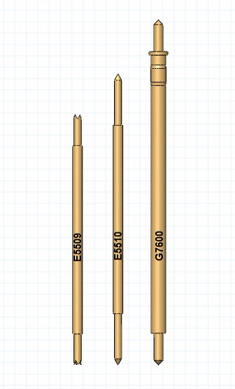
Interface Contacts
|
Interface Contacts |
||||||
|
Probe Series |
Initial Length |
Operating Position |
Operating |
|||
|
(inch/mm) |
(inch/mm) |
Spring Force |
||||
|
.730" |
18.54 |
.680" |
17.27 |
100g |
3.5oz |
|
|
E5510 |
.848" |
21.54 |
.788" |
20.00 |
30g |
1.0oz |
|
.954" |
24.23 |
.850" |
21.59 |
25g |
0.9oz |
|
Choosing a Spring Probe
The choice of spring probe will determine the maximum frequency that a socket can operate. This is usually marked as the pin bandwidth where the insertion loss on the pin reaches -1dB.
Our pin designs are each characterized on a VNA for frequency bandwidth limits. We also simulate our pins with a 3D solver and model of our customer’s pin configuration, drill cavity and socket base material. The VNA measurements give us our measured pin frequency limits and the simulations confirm our performance and allows us to extend the performance with improvements we can make adjusting the structure PCB board or socket impedance.
10 GHz Test Socket
Socket frequency performance primarily is a function of the length of the contact probe. This applies to a socket design without impedance control or tuning. Almost all the probes Signal Integrity uses in their socket library achieve at least a 10 GHz operating point. There are exceptions and our engineers recommend the right probe for the application at hand. There are reasons for using long probes with lots of travel vs. choosing a short probe that operates at a frequency well above the device requirements. In any socket design, reliable first touch contact is a primary goal and the conditions of the part under test may dictate longer probes and compensation for some loss in bandwidth.
20 GHz to 40 GHz Test Sockets
As frequencies increase above 20 GHz, fewer reliable options are available for long life, large travel probes that can achieve this bandwidth limit.
Signal Integrity offers 13 probe design selections at pitches from 0.3 mm to 1.0 mm that are measured at 18 GHz or through > 40 GHz. These probes are designed for applications requiring high bandwidth RF micro Wave and millimeter Wave carrier frequencies or the capability to handle enough power in the 5th harmonic of a serial bit stream. These pins can handle greater than 2.0 amps continuous current per pin, with some 1.0 and 0.8 mm pitch pins capable of current capacity up to 9 amps. These pins are targeted to socket designs for LGA or BGA arrays that require coverage of very high IO speeds and large per pin power consumption with the same probe pin.
Operation Above 40 GHz
Signal Integrity offers solutions up to 80 GHz Bandwidth. These parts require active participation with the customer in pre-design simulation and layout as well as socket housing design. We offer 4 probes between 1.0 mm and 1.5 mm in length with up to 0.2 mm of travel for applications that need bandwidth above 40 GHz.
Current carrying Capacity of Signal Integrity Spring Probes
The Continuous current capacity of a spring probe contact can be specified by measuring either temperature rise or spring force deterioration. The first and most conservative is the temperature measurement. Current is forced to the probe and the temperature rise is measured. Signal Integrity uses a 20 decree C rise in temperature to specify the maximum current carrying capacity.
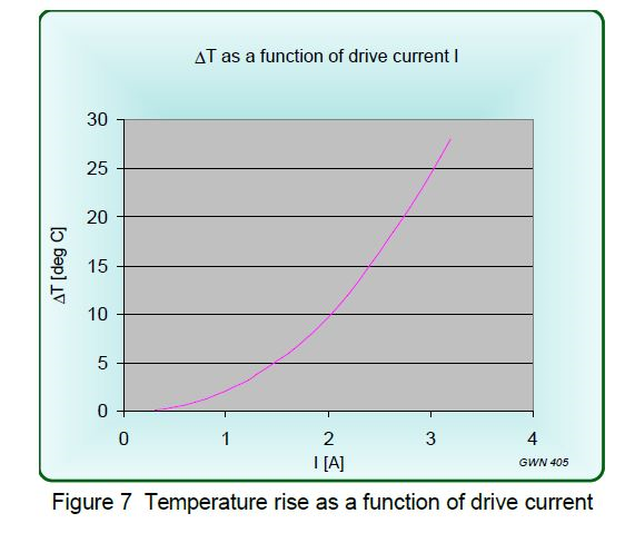
Here is a temperature curve for one of our probes, the E5544. This probe is used in applications up to 50 GHz and there is per pin margin up to above 3A continuous current.
Attention to the design details, insuring that the spring in the probe is not in the conducting path, using thick clad material or thick consistent hard gold plating on the bearing surfaces enable SII probes to handle more continuous current
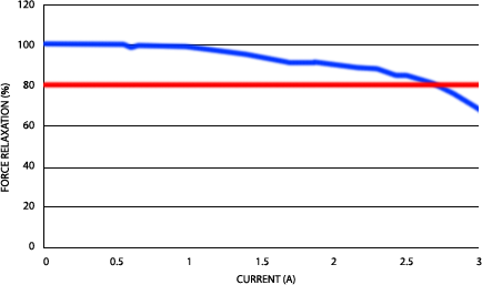
The second method of specifying continuous current is to ramp the current through the pin and measure the point where the spring force reduces some percentage. This si the force relaxation method and does not need a temperature probe which is often very difficult to mount on these very small structures.
Signal Integrity Probes use the temperature method for determining continuous current. Almost every spring probe in our catalog can attain a 3A continuous current measured by force deflection method. In addition, our fine pitch pins can be doubled on device pads for lower inductance and greater current carrying capability.
5A Continuous Current Probes
Signal Integrity can design and manufacture sockets, selecting from 8 of our spring probes models that can operate from 4.5A to over 6.0 amps. Our probe catalog gives us the flexibility that these high-power probes also operate well over 10 GHz some as high as 40 GHz. These are excellent probes for large high power high speed arrays achieving long lifetime, IO and power performance in the most demanding production test environments for very large packages with planarity to consider.
Delivering 5 amps of continuous current in a fine pitch pin allows our socket designs to use more pins per power pad to deliver even higher continuous current. These sockets can focus on delivering the current needed for continuous power delivery and high current pulse testing for all types of power and power control, regulators, converters, MOSFET, IGBT and JFET devices.
Signal integrity can deliver high current board to board connectors using these probes.
8A Continuous Current Probes
Signal Integrity can design and manufacture sockets, selecting from 7 of our 0.8mm and 1.0mm spring probes models that can operate from 6A to over 8.0 amps of continuous current. These high-power probes also operate well over 130 GHz some as high as 30 GHz. These are excellent probes for large high power high speed arrays achieving long lifetime, IO and power performance in the most demanding production test environments for very large packages with planarity to consider. Another strong reason to use a socket with pins that have such a performance range is
Delivering 5 amps of continuous current in a fine pitch pin allows our socket designs to use more pins per power pad to deliver even higher continuous current. These sockets can focus on delivering the current needed for continuous power delivery and high current pulse testing for all types of power and power control, regulators, DC-DC converters, MOSFET, IGBT and JFET devices.
Signal integrity also designs and manufactures high current board to board connectors using our probe library these low contact resistance high current spring probes.
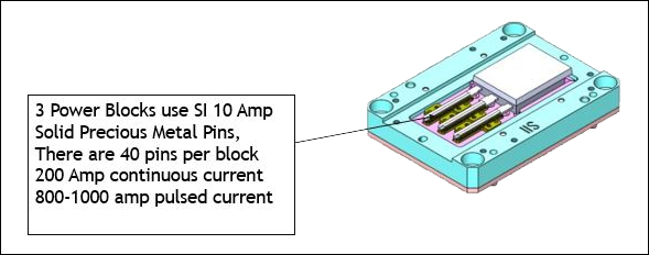
800 Amp Pulsed Current Contactors
Signal Integrity has developed connector power block modules for TO and STO devices in the high current applications for EV and charging systems. These power block modules are integrated into sockets to deliver very high pulsed currents from 600 to 1000 amps for short duration pulses
Signal Integrity developed these power blocks with very low inductance and contact materials with very low resistance to be able to switch very high currents, operate at greater than 100 amps continuous current. These connectors deliver this performance with very low inductance, proper material and ablative surfaces. These are for very high volume and designed to operate for > 1,000,000 cycles.